What’s Inside an F1 Gearbox (and How it Works)
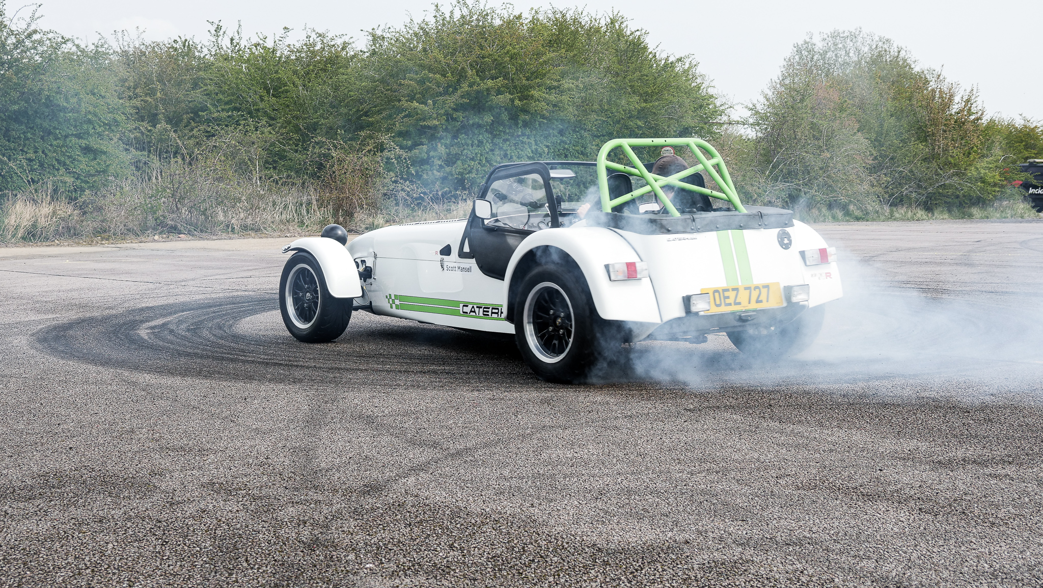
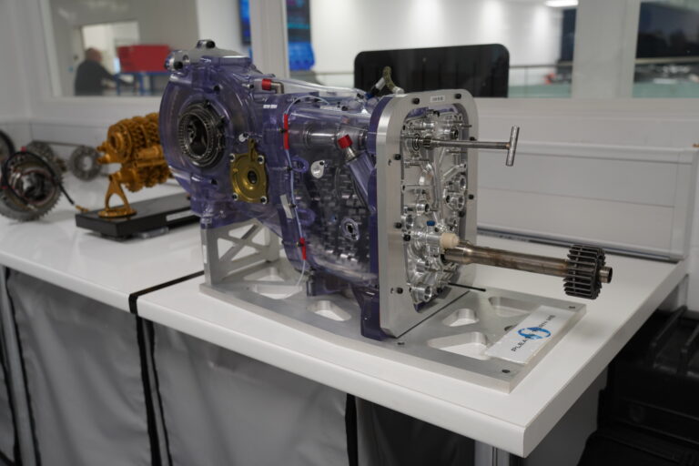
In this video, I’m going to take a look at what’s inside this Formula One gearbox and explain a little bit about how it works. Today, I’m in the workshop of Mansell Motorsport who restore and look after many Formula One cars from the mid-’90s to the mid-2000s. They’ve been kind enough to give me this 1997 Jordan F1 Gearbox for me to open up and have a look at how the internals actually work.
Before I get into taking this gearbox apart, I think it’s important to understand the position of the gearbox within the Formula One car itself. As you know, at the front of the Formula One car where the driver sits, we have the tub which is made out of carbon fiber. Then behind that, on four studs, we have the engine bolted directly onto the tub. Behind the engine, we have the gearbox bolted directly to the engine. All of these parts are stressed members. They’re part of the chassis, meaning that the rear suspension is in fact bolted directly on to the gearbox.
This is the front of the gearbox casing. It’s made out of cast magnesium. You can see this input shaft at the bottom just down here. This is connected directly to engine and it’s where the power comes through from the engine onto the layshaft of the gearbox. In terms of changing gear, we need to head around to the side of the gearbox. What you can see just here is the change cylinder. The driver makes the shift request with the paddles on the steering wheel, either up or down. It then goes through the GCU. The change cylinder here, which, in this case, is pneumatic with air either fires the gears down or up the gearbox.
If I just put this handle on here, if you watch the end of the cylinder, you can see it moving. Obviously, the force would come from this side and it would change the gears up or down. Before we can get into the gear cluster, I need to take off the rear diff housing. In this section of the gearbox and the rear diff housing, the diff gear and diff would sit in here. In the side here come the driveshaft. We have the driveshafts would then go out to the uprights, which are then, obviously, attached to the wheels and so the power can go through the gearbox, the diff, and into the track.
Now, I’ve removed all of the nuts from the diff casing. Time to try and take it off. Now, you can see that I’ve opened up the diff casing away from the gearbox casing to my right. You can see here that this is the main shaft that comes out the top of the gearbox. This gear, this bevel gear, drives this gear, which is then, obviously, connected to this gear, which then would go behind here onto the diff gear and rotate here, which then goes onto the drive shafts, which then, obviously, goes to the uprights, and through the wheels, and into the racetrack.
This, just on the top, inside the gearbox casing here, is the gearbox oil tank. You can see it’s got an opening here. Well, behind that, if you imagine back here the diff gear coming around and around just in this position here, then all the oil that collects then gets flicked into the gearbox oil tank for then distribution around the rest of the gearbox.
If you look closely, these nuts here and take the oil tank off at the top. The cassette should come out here. We’ve got the main shaft here and the layshaft at the bottom, which I’ll explain once we’ve taken out, as it’s a little bit easier to explain once you can see all of the moving parts.
Here we go. Let’s have a look at those gears.
First of all, you can see here that we have the layshaft that runs across the bottom. That turns the main shaft that runs across here. The layshaft is the one that’s connected to the engine, the engine comes out of here and powers this layshaft. Now, none of the gears on here actually turn away from the shaft. They’re directly splined onto the shaft itself. From the size of them, with this one being the smallest just here, you can see that this is first gear, these pair of gears. This is second here and then we jump across here, third, fourth, fifth, sixth and seventh with these gears just here. The power from the engine drives the layshaft here which then turns all the gears on this top shaft.
I’ve just put this piece of wood in place so you can actually see the gears turned. We can see here because all the gears are turning freely, you imagine the engine power coming here, we’re spinning all the gears but nothing on this left-hand-side is going into the diff. You can see here that the car or the gearbox is actually in neutral because there’s no power or no drive coming at the back of the gearbox here and going to the diff.
How do we actually change gear? Well, I showed you earlier on the change cylinder on the outside of the gearbox that moves forwards and backwards and then shifted the change mechanism. Well through the internals of the gearbox that’s actually connected to this. This is the barrel and the selector shaft along here. As the change goes through the change cylinder, it actually comes here and moves this barrel around which then moves this piece here which is the selector fork across.
We’ve got the engine running. The power is coming through here onto the layshaft, the gears are turning on the main shaft at the top but the gear at the back here, the main isn’t actually turning. It’s just the gears that are spinning on top of the main shaft, we’re in neutral. Then the driver pulls a gear and it goes into first gear. You can see the selector fork here move across and we take first gear just here. Let me simulate the engine moving. Pick the shaft up again. You can see that the gear, the main shaft is actually rotating now all the way through, we’re in-gear. Then the driver selects another gear, the selector fork moves across and we take second gear. Sorry, it just fell out. Now, at the back, you can see that the main shaft is spinning again. Then we go up another gear and if you watch this selector fork, we head into third gear and again, it’s all locked up on that main barrel and we take third gear. Again into fourth, you can see this selector fork move across fourth, fifth, sixth and seventh. We’re in seventh gear, sixth gear, fifth gear, fourth gear, third gear, second gear and first gear’s just gone dog to dog.
That’s a really good way to show it. You can see that we’ve gone from first, second, third, fourth, fifth, sixth and seventh. You can see there that the timing is obviously absolutely perfect. When we go from one gear across into second– now watch this selector fork and this selector fork. We go from second here, that then comes into the neutral position into between these two dogs. Then the third gear moves across. That then moves away from the dogs and disengages this gear just before the fourth selector fork moves across and engages fourth gear and again the process continues all the way along. That’s an absolutely beautiful piece of engineering that you can see there.
To better explain the gears on the main shaft which is the more complex of the two shafts. I’ve gone and picked up a few spares off the shelf. On the layshaft, you can see here that this hub is splined. The main shaft has spline like this and this hub fits over the main shaft. Then you can see here that we are splined on the outside of the hub as well. Those splines are so this dog ring can fit over the top and stay have movements side to side, lateral movements side to side but stay connected and can drive the gear that’s attached to this hub.
Then on this section of the hub, we have a bearing as you can see in here that spins and then we have the gear that goes over the bearing. As you could see before, the gear is actually, let me just remove this dog ring, the gear is actually not connected to the hub. It is not driven all the time by the shaft. Then when we put on the dog ring and this is how we can change gear to select a fork that I showed you earlier and actually it goes over the dog ring like this. The selector fork moves across and then engages the gear, which means that the gear then drives the shaft which then goes straight to the diff and can drive the rear wheels.
One important thing to note is the cut of the dog just here, you can see that it isn’t at 90 degrees to the gate it’s actually cut like this. Now, the reason for that it’s when the gear and the dog ring come together when it’s being driven, when it’s loaded they actually pull each other together and when you put in seven or eight hundred brake hosepipe through these gears, it’s obviously very important that mechanically they drive each other together.
That’s all for this video. Thank you very much for watching and if you did enjoy this type of video, please let me know in the comments below and be sure to subscribe if you haven’t already. Thanks and I will see you next time.


